
Band-Pass and Band-Reject Filter Design and Analysis
Overview
Overview
I had to design, construct, and analyze a band-pass RLC filter as well as a band-reject (notch) RLC filter for this project. The goal was to build the circuits on a breadboard, compute component values from given resonant frequencies and quality factor requirements, and use oscilloscope-generated Bode graphs to confirm the circuits' frequency-selective behavior. I was able to see how RLC circuits can be used to either pass or reject particular frequency ranges by contrasting theoretical calculations with measured frequency response data. My knowledge of resonance, bandwidth, quality factor, and frequency response analysis has improved as a result of this research.
1. Calculate the Filter Component Values
The resonance frequency for the band-reject filter was 66π krad/s. I determined a resistance value of roughly 4.75 Ω and confirmed the necessary resonance condition using a 470 µH inductor and a 47 nF capacitor. The final design used a 10 Ω resistor because this value was not available. These computations served as the basis for building both filters.
I began by figuring out the component values needed to meet the quality factor and resonant frequency criteria. The band-pass filter had a quality factor of 10 and a target resonant frequency of 42π krad/s. I determined the necessary resistance to be roughly 3290 Ω using a 1 mH inductor and 47 nF capacitor. I used the closest standard resistor value of 3.3 kΩ.
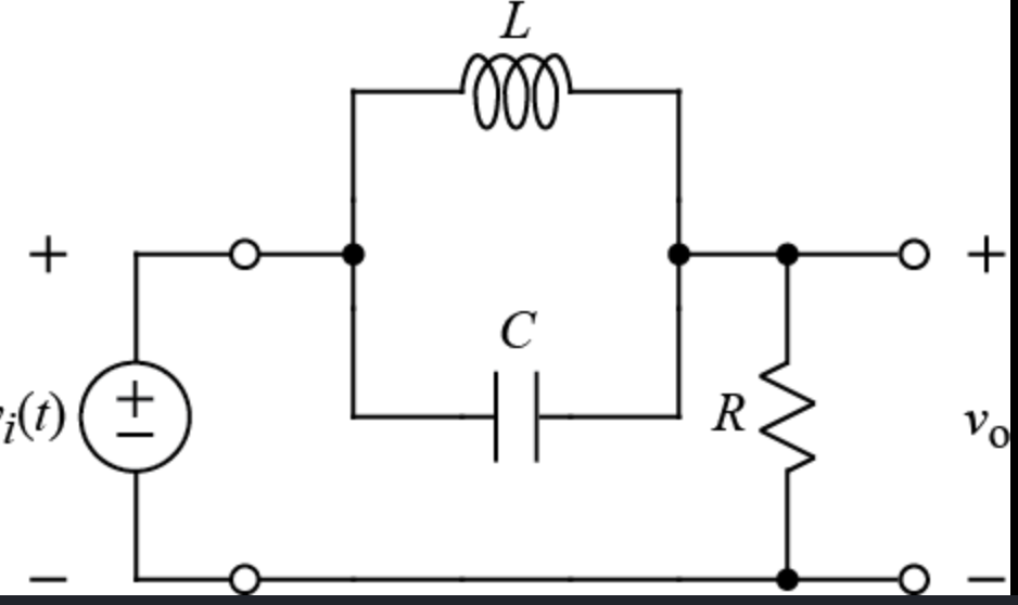
ref for curict design
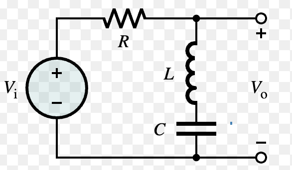
ref for curict design
2. Construct the Band-Pass Filter

I used a 1 mH inductor, a 47 nF capacitor, and a 3.3 kΩ resistor to create the band-pass filter after finishing the computations. The circuit was set up to allow frequencies close to the resonance frequency to flow through while attenuating frequencies above and below that range. I learned how resonance may be utilized to selectively pass a limited range of frequencies by building this circuit. It also gave practical experience wiring RLC circuits and prepping them for frequency response testing.
3. Construct the Band-Reject (Notch) Filter
After building the band-pass filter, I assembled the band-reject filter using a 470 µH inductor, 47 nF capacitor, and 10 Ω resistor. This circuit was designed to suppress signals close to the resonance frequency while permitting frequencies outside of that range to pass, in contrast to the band-pass design. Resonance can also be utilized to exclude undesirable frequencies from a signal, as this circuit showed. I was able to have a better understanding of the distinctions between frequency selection and frequency rejection strategies by building both filters.
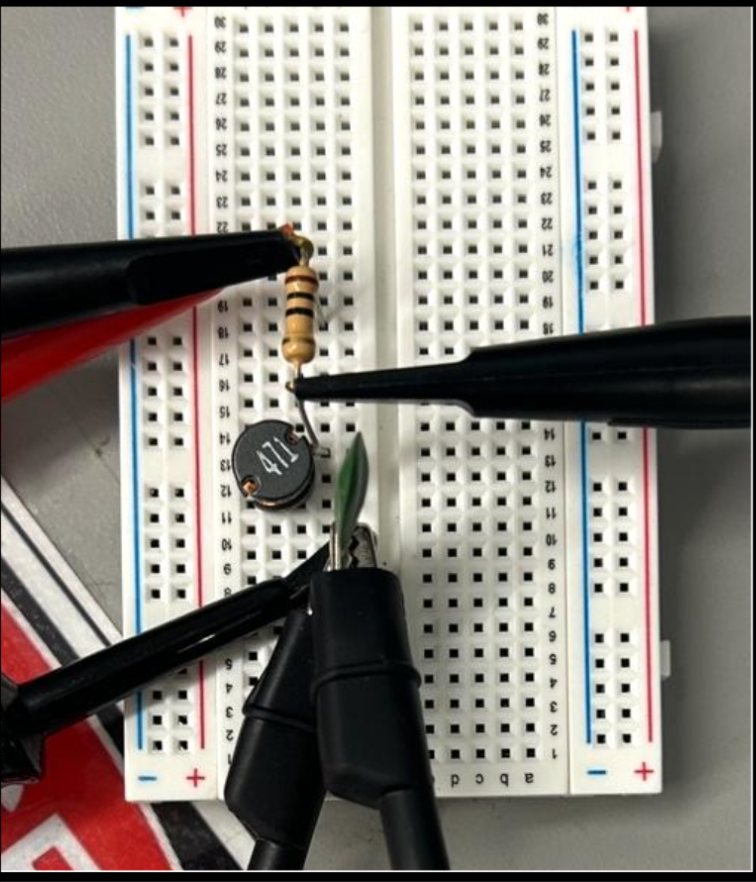
ref for curict design
4. Construct the Band-Pass Filter
I used a 1 mH inductor, a 47 nF capacitor, and a 3.3 kΩ resistor to create the band-pass filter after finishing the computations. The circuit was set up to allow frequencies close to the resonance frequency to flow through while attenuating frequencies above and below that range. I learned how resonance may be utilized to selectively pass a limited range of frequencies by building this circuit. It also gave practical experience wiring RLC circuits and prepping them for frequency response testing.
5. Analyze Frequency Response Using an Oscilloscope
After constructing both circuits, I created Bode graphs using the oscilloscope's Frequency Response Analysis feature to see how each filter reacted to frequency variations.
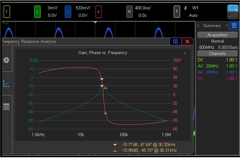
The gain of the band-pass filter clearly peaked close to its resonant frequency. The gain dramatically increased as the input frequency got closer to resonance before declining once further at higher frequencies. The -3 dB points, which happened between roughly 30 kHz and 36 kHz, were used to determine the observed bandwidth. Around resonance, the phase response also changed from positive to negative values, exhibiting the typical behavior of a band-pass filter.
Band-Pass Filter Results
The frequency response of the band-reject filter showed a distinct notch. The gain decreased dramatically close to the resonance frequency of roughly 33–35 kHz, indicating successful attenuation of signals in that frequency range, although it stayed largely constant across the majority of frequencies. The anticipated notch filter behavior was confirmed by the phase response, which also altered significantly around resonance.

Band-Reject Filter Results
6. Results, Analysis, and Further Reading
Lastly, I assessed the effectiveness of both filters by comparing the measured frequency responses with my theoretical computations. The band-pass filter effectively attenuated sounds outside of the resonance region while permitting frequencies close to resonance to pass. On the other hand, the band-reject filter effectively reduced signals close to resonance while permitting frequencies above and below the rejection band to flow through.
Theoretical and observed values differed slightly, although this was to be expected given component tolerances, conventional component substitutions, breadboard parasitic effects, and measurement error. Despite these issues, both filters showed the usefulness of resonance-based filter design and operated in accordance with their anticipated frequency response characteristics.
This project gave me practical experience creating Bode plots, understanding frequency response data, calculating resonant frequencies and quality factors, and developing RLC filters. All things considered, this research improved my comprehension of resonance, bandwidth, and frequency-selective circuit design while giving me invaluable experience tying theoretical analysis to practical observations.
The full laboratory report offers comprehensive project documentation if you're interested in delving deeper into the design process, computations, oscilloscope measurements, frequency response graphs, and in-depth experimental analysis.
Key Steps
Tools and Components Used
-
Breadboard
-
Function Generator
-
Oscilloscope
-
1 mH Inductor
-
470 µH Inductor
-
47 nF Capacitors
-
3.3 kΩ Resistor
-
10 Ω Resistor
-
Connecting Wires