top of page

RC & RL Filter Design and Analysis
Overview
Overview
I had to design, construct, and analyze both an RC high-pass filter and an RL low-pass filter for this project. The goal was to build the circuits on a breadboard, determine the necessary component values from the specified cutoff frequencies, and use an oscilloscope to confirm their functionality. By comparing theoretical calculations with measured frequency response data, I was able to determine how inductors and capacitors affect signal behavior at different frequencies. My knowledge of passive filter design, frequency response analysis, circuit construction, and laboratory testing methods has improved as a result of this research.
Tools and Components Used
-
Breadboard
-
Function Generator
-
Oscilloscope
-
170 Ω Resistor
-
7.5 kΩ Resistor
-
4.7 mH Inductor
-
47 nF Capacitor
-
Connecting Wires
Key Steps
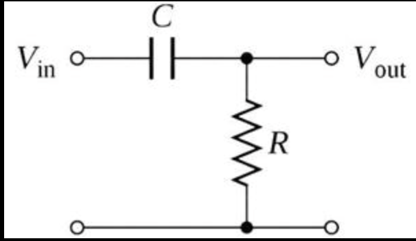
I proceeded to the RC filter after finishing the RL computations. I determined a resistance value of roughly 7525 Ω using a 47 nF capacitor and the given cutoff frequency of 900π rad/s. In the final design, 7.5 kΩ was the closest standard resistor that could be found. These computations served as the basis for building both filter circuits.

ref for curict design
ref for curict design
1. Calculate the Filter Component Values
I began by figuring out the component values needed to reach each filter's designated cutoff frequencies. The target cutoff frequency for the RL filter was 12000π rad/s, and I determined a resistance value of roughly 177 Ω using a 4.7 mH inductor that was readily available. I chose the nearest resistor, 170 Ω, as this was not a typical resistor value.
2. Construct the RL Low-Pass Filter
After finishing the calculations, I put together the RL circuit on a breadboard by connecting the 4.7 mH inductor and 170 Ω resistor in series. A low-pass filter arrangement was created by measuring the output voltage across the resistor.
This circuit was designed to attenuate higher-frequency signals while permitting low-frequency signals to flow through. The inductive reactance rises with frequency, which lowers current flow and lowers output voltage. I gained hands-on experience with component placement, circuit assembly, and troubleshooting hardware connections by building this circuit.

3. Construct the RC High-Pass Filter
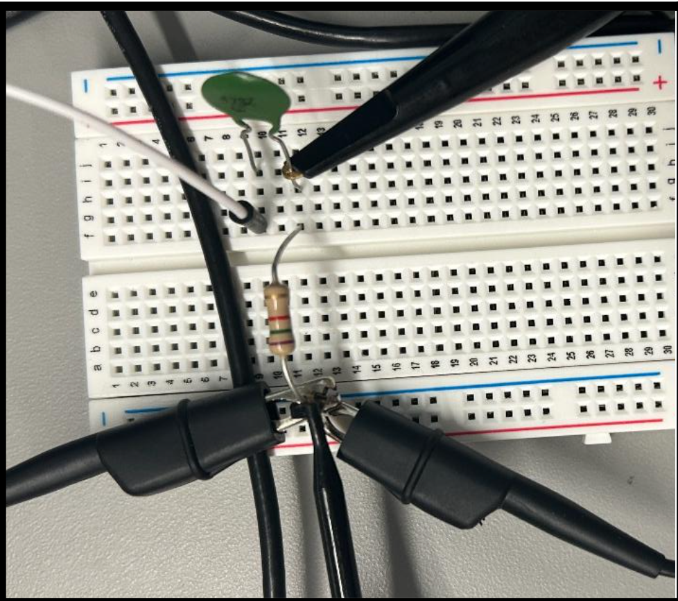
After finishing the RL filter, I used a 47 nF capacitor and a 7.5 kΩ resistor to construct the RC filter. A high-pass filter arrangement was created by measuring the output voltage across the resistor.
This filter was intended to reduce low-frequency transmissions while permitting higher-frequency signals to pass, in contrast to the RL circuit. The capacitor restricts current flow and exhibits a strong reactance at low frequencies. More signal might come across the resistor as the frequency rises because the capacitive reactance falls. Building both circuits improved my comprehension of the various functions that capacitors and inductors have in filter construction.
4. Analyze Frequency Response Using an Oscilloscope
After constructing both circuits, I created Bode graphs using the oscilloscope's Frequency Response Analysis feature to see how each filter reacted to frequency variations.

I proceeded to the RC filter after finishing the RL computations. I determined a resistance value of roughly 7525 Ω using a 47 nF capacitor and the given cutoff frequency of 900π rad/s. In the final design, 7.5 kΩ was the closest standard resistor that could be found. These computations served as the basis for building both filter circuits.
RL Low-Pass Filter Results
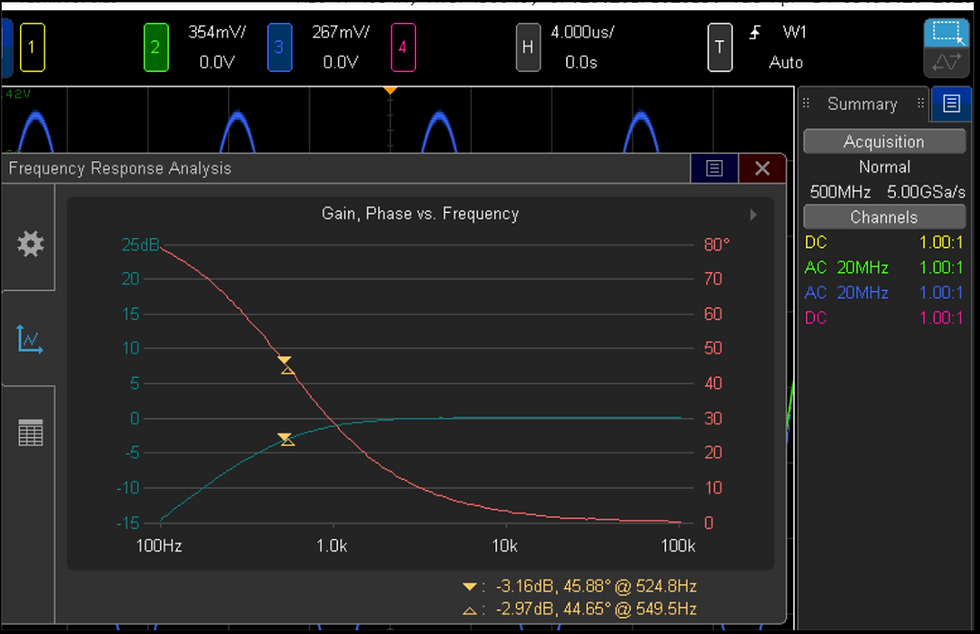
As a high-pass filter, the RC circuit effectively attenuated low-frequency signals while permitting higher-frequency signals to flow through. With a phase shift of about 45°, the observed cutoff frequency was roughly 540 Hz. The graph demonstrated the anticipated high-pass response by showing the gain rising with frequency.
RC High-Pass Filter Results
In order to assess the effectiveness of both filters, I finally compared the measured cutoff frequencies and phase shifts with my theoretical calculations. While the RC circuit effectively functioned as a high-pass filter, attenuating low-frequency signals and permitting higher-frequency signals to pass, the RL circuit effectively functioned as a low-pass filter, permitting low-frequency signals to pass while attenuating higher-frequency signals. The measured cutoff frequencies for the RL filter and RC filter, which were roughly 5.3 kHz and 540 Hz, respectively, nearly matched the predicted theoretical values.
Breadboard parasitic effects, measurement uncertainty, and component tolerances all contributed to the slight discrepancies between the measured and estimated findings. Both filters exhibited the expected frequency response characteristics in spite of these circumstances, confirming the design calculations and proving the usefulness of passive filter theory.
I learned how to calculate filter parameters, build circuits on a breadboard, create and analyze Bode plots, and use oscilloscope measurements to confirm circuit performance through this project. All things considered, this study improved my comprehension of frequency-selective circuits and gave me useful experience relating theoretical analysis to actual experimental outcomes.
5. Results, Analysis, and Further Reading
The full laboratory report offers comprehensive project documentation if you're interested in delving deeper into the design process, computations, oscilloscope measurements, frequency response graphs, and in-depth experimental analysis.
bottom of page