Overview
As part of this project, I had to develop and test a first-order RC circuit utilizing a 470 nF capacitor and a time constant of 5 ms. Additionally, a 20 Hz square wave input with a 50% duty cycle and a voltage range of 0 V to 5 V was required by the laboratory. Prior to building the circuit, I had to figure out the right resistor value, forecast how the circuit would charge and discharge, and compute important performance metrics like the capacitor voltage at predetermined intervals.
In order to finish the project, I utilized an oscilloscope to examine the circuit's transient response, developed and constructed the RC circuit on a breadboard, and set up the necessary input signal using a function generator. I then verified ideas like the RC time constant, exponential charging and discharging behavior, and steady-state response by comparing measured waveform data with theoretical computations. Through this project, I was able to validate performance using lab equipment and apply circuit theory to a real-world electrical system.
Tools and Technologies Used
-
Breadboard
-
Resistor (~10 kΩ)
-
Capacitor (470 nF)
-
Function Generator
-
Oscilloscope
-
Jumper Wires
-
RC Time Constant Analysis
-
Exponential Charging and Discharging Equations
KEY STEPS
1. Developed the Logic Functions
I began by resolving the project's main design requirement, which was to use a 470 nF capacitor to create a first-order RC circuit with a time constant of 5 ms. I determined the ideal resistance required to meet the necessary time constant using the RC time constant equation (τ=RC). I chose the closest resistor value for the experiment because the computed value was roughly 10.6 kΩ. Before building the circuit, I was able to forecast how rapidly the capacitor would charge and discharge thanks to this preliminary research.
2. Analyzed the Design Requirements
I examined the laboratory requirements for the input signal after figuring out the resistor value. A 20 Hz square wave with a 50% duty cycle and a voltage range of 0 V to 5 V had to be produced by the function generator. I computed the signal period and the duration of the signal's high and low states using these parameters. In order to ascertain whether the capacitor would have enough time to achieve nearly steady-state conditions during both charging and discharging, I then compared these time intervals to the circuit's 5 ms time constant. Before any hardware testing was done, this analysis assisted in determining the circuit's expected behavior.
3. Constructed the RC Circuit
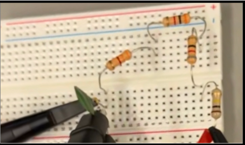
Once the theoretical calculations were complete, I assembled the first-order RC circuit on a breadboard using the selected resistor and capacitor. The resistor and capacitor were connected in series according to the circuit requirements, and the function generator was connected as the input source. During construction, I carefully verified all wiring connections, component placement, and grounding to ensure the circuit would accurately represent the intended design and minimize measurement errors during testing.
4. Collected Waveform Measurements
After constructing the circuit, I connected an oscilloscope to concurrently monitor the input voltage and the capacitor voltage and set the function generator to the necessary lab settings. I was able to see firsthand how the capacitor reacted to variations in the input signal by displaying both signals on the oscilloscope. Throughout the experiment, this configuration allowed for a clear visual comparison of the transient response of the capacitor and the square-wave input.
For a deeper dive into the design process, calculations, oscilloscope measurements, and detailed experimental analysis, you can view the full laboratory report that I created for this project
View My Full Laboratory Report
5. Tested and Verified Circuit Performance
I examined the charging and discharging behavior of the capacitor while the circuit was in operation, comparing the observed waveforms to theoretical expectations. Instead of changing instantly, the capacitor displayed the anticipated exponential charging and discharging curves as the input signal alternated between high and low voltage levels. I measured the signal frequency, period, and capacitor voltage at t=2τ, among other important quantities listed in the lab requirements. The accuracy of the circuit's reaction was confirmed by comparing these measurements with theoretical computations.
As anticipated during the pre-laboratory investigation, the oscilloscope findings demonstrated that the capacitor had enough time to attain steady-state conditions during each cycle. The circuit satisfied the design specifications and functioned in accordance with accepted RC circuit theory, as demonstrated by the observed waveforms' close match to the anticipated first-order response.
Analysis and Verification of a First-Order RC Circuit Using Time Constant and Waveform Measurements