
Overview
Using two Blackboard FPGA development boards connected by PMOD GPIO, I created a traffic light control system for this project. The goal was to replicate a real-world traffic crossroads in which the East/West traffic lights were controlled by one board and the North/South traffic lights by another. The boards maintained synchronization by exchanging traffic light status signals via PMODC pins using memory-mapped GPIO registers.
My knowledge of GPIO communication, memory-mapped I/O, interprocessor communication, embedded C programming, and real-time control systems has improved as a result of this project. Additionally, it gave me useful expertise coordinating several microcontrollers to function as a single embedded system.
Tools and Technologies Used
-
Embedded C
-
FPGA Blackboard Development Board
-
GPIO Communication
-
PMOD Interface
-
Memory-Mapped I/O
-
Vitis Development Environment
-
LED Control
-
Interprocessor Communication
-
Real-Time Embedded Systems
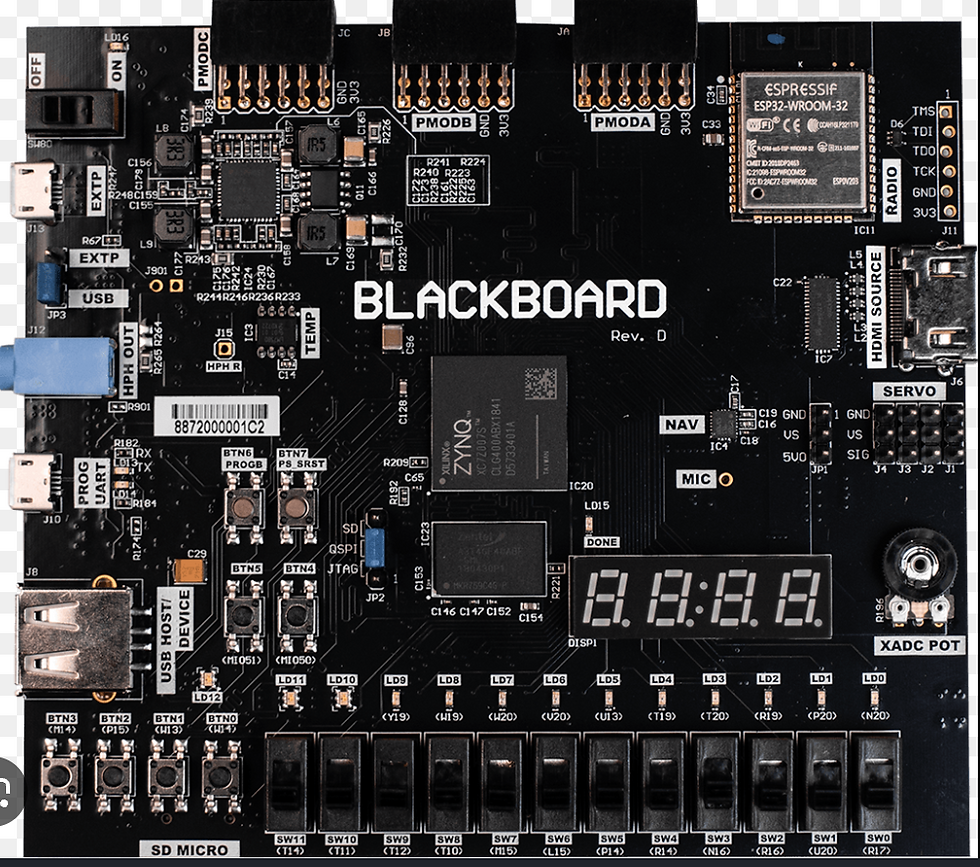
board used!
KEY STEPS
1. Configure GPIO Hardware and Memory-Mapped Registers

I began by establishing the memory-mapped GPIO registers that are used to control the PMOD communication pins and the onboard RGB LED. LED12 was controlled by GPIO Bank 0, and communication between the two development boards was set up on GPIO Bank 2. I made sure the hardware began in a safe state with the traffic light set to red by configuring the direction, enable, and output registers during initialization.
2. Implement Traffic Light LED Control
I created a method to manage the onboard RGB LED after setting up the hardware. Red, yellow, and green traffic light statuses were represented by the system using various combinations of LED bits. To avoid conflicting outputs, the function clears any previous LED values before adding a new color.
The current traffic light was shown on both development boards using this function as the basis.
3. Implement GPIO Message Passing Between Boards
I created the communication mechanism that enabled the North/South controller to send traffic light states to the East/West controller after LED control was operating properly. The East/West board continuously observed matching PMOD input pins to ascertain which signal was active, while the North/South board used PMOD output pins to transmit red, yellow, and green status signals.
This stage showed me how CPUs can communicate using basic GPIO connectors and introduced me to embedded message passing.
4. Create the Traffic Light Control Sequences
I put the traffic light timing sequence into place after the boards had established communication. While sending the proper signal to the East/West controller, the North/South controller alternated between red, green, and yellow states. These signals were continuously received by the East/West controller, which adjusted its own traffic light.
In order to mimic the behavior of a genuine traffic crossroads and guarantee safe traffic flow, the sequence was created so that only one way could display a green light at a time.
PUT ALL TOGETHER
Note: To view the complete code and run it, scroll down within the box if the code appears to be shrinking.
Results, Analysis, and Further Reading
Using PMOD GPIO connections, the finished system effectively demonstrated communication between two Blackboard development boards. GPIO output pins were used by the North/South controller to send traffic light conditions, while GPIO input pins were used by the East/West controller to receive and interpret those signals. In order to perfectly mimic the behavior of a genuine traffic intersection, the coordinated operation made sure that only one direction flashed a green light at any given time.
I learned a lot about memory-mapped hardware registers, GPIO settings, embedded communication protocols, and multi-processor coordination from this project. Learning how several embedded systems may communicate and cooperate to control a bigger system was one of the most beneficial parts of this project.In general, this research improved my knowledge of hardware interface, embedded system communication, and real-time control applications.
The entire laboratory report offers comprehensive project documentation if you want to delve deeper into the GPIO implementation, PMOD communication design, timing sequences, and embedded C source code.
5. Integrate and Test the Complete Stoplight System
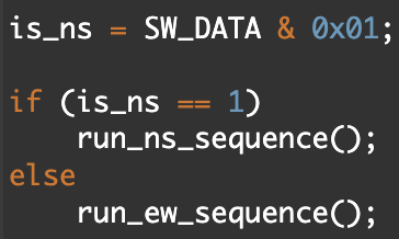
Lastly, I incorporated every system component into the main application. To decide whether the board should function as an East/West controller or a North/South controller, the software examines switch SW0 at startup. The board either generates the traffic light sequence or listens for incoming signals from the other board, depending on the switch position.
I confirmed that traffic light states were accurately transferred, received, and displayed after testing both boards simultaneously. The finished solution used GPIO message passing to imitate the behavior of an actual traffic crossing while properly synchronizing both controllers.


Dual-Board Traffic Light Control System Using GPIO Communication