


Overview
For this project, I created an Embedded C stopwatch application that used memory-mapped I/O to connect directly with a four-digit seven-segment display and push buttons on an FPGA development board. The stopwatch had to start when BT0 was pressed, pause when BT1 was pressed, reset when BT2 was pressed while the stopwatch was stopped, show values in Binary Coded Decimal (BCD) format, and increase once every second. The project concentrated on bit masking, register manipulation, low-level hardware interfacing, and real-time embedded system control.
I later used HTML, CSS, and JavaScript to rebuild the stopwatch interface so that the identical start, pause, and reset features could be seen and tested on a web browser, helping to illustrate the finished system.
Tools and Technologies Used
-
Embedded C
-
FPGA Blackboard Platform
-
Memory-Mapped I/O
-
Seven-Segment Display
-
Push Buttons
-
Vitis Development Environment
-
HTML
-
CSS
-
JavaScript
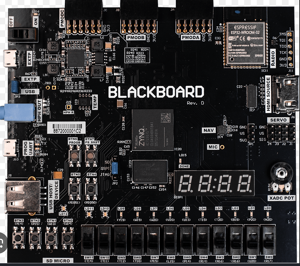
board used!
KEY STEPS
1. Configure Memory-Mapped Hardware Access

I began by establishing the memory addresses for the push-button and seven-segment display registers. Through memory-mapped I/O, these memory addresses enabled direct communication between the ARM CPU and FPGA peripherals. I was able to read button states and change display values without the need for further drivers or libraries by constructing register definitions as pointers.
2. Create Single-Digit Display Functions
I created a function that could write individual numbers to designated locations on the seven-segment display after establishing hardware access. Only the desired digit was cleared and updated by the function using bit masking and bit shifting, keeping the other display values unaltered. This strengthened my comprehension of register-level programming approaches and gave me exact control over every display location.
3. Implement BCD Conversion for Multi-Digit Display
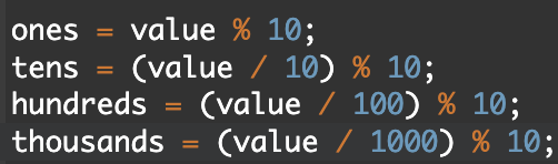
I developed a method that converted an integer value into Binary Coded Decimal format after each digit control was operational. Before transmitting each digit to the proper display location, the function divided the stopwatch value into ones, tens, hundreds, and thousands of digits. This made that the stopwatch accurately counted and showed values in decimal format for each of the four digits.
4. Implement Stopwatch Control Logic
I created the primary stopwatch control logic after finishing the display functions. The software used bit masking to identify which button was pressed while continuously monitoring the push-button register. The stopwatch was begun by BT0, paused by BT1, and only when the stopwatch was stopped did BT2 restart the count. The timing characteristic required by the lab was created by adding a one-second delay.
PUT ALL TOGETHER
Note: To view the complete code and run it, scroll down within the box if the code appears to be shrinking.


Results, Analysis, and Further Reading
The finished stopwatch satisfied all laboratory requirements and successfully interfaced with FPGA hardware via memory-mapped I/O. All push-button controls worked as intended, the timer increased once per second, and the display updated accurately in four-digit BCD format. Memory-mapped register access, bit masking, pointer-based hardware interface, modular function design, and real-time polling techniques were among the important embedded systems principles that were reinforced by the project.
Through this project, I improved my knowledge of low-level system programming and FPGA-based embedded design while gaining useful experience creating software that directly interacts with hardware devices.
For a deeper dive into the memory-mapped I/O implementation, BCD conversion process, register manipulation techniques, and complete Embedded C source code, the full laboratory report provides detailed documentation of the entire project
FPGA Stopwatch Using Memory-Mapped I/O